Introduction to VoIP protocols
This technical paper describes the VoIP protocols employed for the transmission of voice samples through an IP based network. We aim to give you the basic grounding needed to further investigate the bandwidth requirements of voice over IP. We do not discuss header compression schemes or layer 2 protocols. Furthermore, this paper only considers IPv4 and not IPv6.
You can carry out many of the calculations described on this page with VoIP Calculator, our voice over IP bandwidth calculator for Windows, available with free upgrades for life for only $59.
Layered model
In common with many communications systems, the protocols involved in Voice over IP (VoIP) follow a layered hierarchy that can be compared with the theoretical model developed by the International Standards Organisation (OSI seven layer model). Breaking a system into defined layers can make it more manageable and flexible. Each layer has its job and does not need a detailed understanding of the layers around it.
For example, IP datagrams can be transported across a variety of link layer systems including PPP, Ethernet and ATM. The link layer protocol is for the most part irrelevant to IP (unless that protocol limits the size of its datagrams), and need not be the same for the first link of a Voice over IP call and the final link of a VoIP call. As always there are exceptions (such as IP over ATM), but we will only consider the simple discreet layered model in this document.
The effect of each layer’s contribution the the communication process is an additional header preceding the information being transmitted. The complete packet that a layer creates (header and data) becomes the data passed to the next level for processing. That layer will then add a header portion, and so on…
We look at each layer, starting at the Network (or Internet) Layer, in the sections that follow.
IP (Internet Protocol)
The Internet Protocol is the lowest level protocol considered in this document and is responsible for the delivery of packets (or datagrams) between host computers. IP is a connection-less protocol, that is, it does not establish a virtual connection through a network prior to commencing transmission; this is the job for higher level protocols.
IP makes no guarantees concerning reliability, flow control, error detection or error correction. The result is that datagrams could arrive at the destination computer out of sequence, with errors or not even arrive at all. Nevertheless, IP succeeds in making the network transparent to the upper layers involved in voice transmission through an IP-based network.
VoIP protocols must use IP (by definition) but IP alone is not well suited to voice. Real time applications such as voice and video require guaranteed connection with consistent delay characteristics. Higher layer protocols address these issues.
The diagram below shows the header that proceeds the data payload to be transmitted. In its most basic form, the header comprises 20 octets. There are optional fields that can be appended to the basic header, but these offer additional capabilities not necessary for VoIP transmission as described in this document.
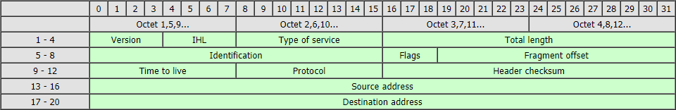
The fields are briefly described below:
- Version
The version of IP being used. For this format header, the version would be 4. - IHL
The length of the IP header in units of four octets (32 bits). For the basic header shown in this diagram, the value would be 5 (each line in the diagram represents four octets). - Type of service
The quality of service requested by the host computer sending the datagram. This is not always effectively supported by routers or Internet Service Providers. - Total length
The length of the datagram, measured in octets, including the header and payload. - Identification
As well as handling the addressing of datagrams between two computers (or hosts), IP needs to handle the splitting of data payloads into smaller packages. This process, known as fragmentation, is required because, although a single IP datagram can handle a theoretical maximum length of 65,515 octets, lower link layer protocols such as Ethernet cannot always handle these large packet sizes. This field is a unique reference number assigned by the sending host to aid in the reassembly of a fragmented datagram. - Flags
These flags indicate whether the datagram may be fragmented and, if so, whether further fragments follow this one. - Fragment offset
This field indicates where in the datagram this fragment belongs. It is measured in units of 8 octets (64 bits). - Time to live
This field indicates the maximum time the datagram is permitted to remain in the internet system. This parameter ensures that a datagram that cannot reach its destination host is given a finite lifetime. - Protocol
This indicates the higher level protocol in use for this datagram. Numbers have been assigned for use with this field to represent such transport layer protocols as TCP and UDP. - Header checksum
This is a checksum covering the header only. - Source address
The IP address of the host that generated this datagram. IPv4 addresses are 32 bits in length and, when written or spoken, a dotted decimal notation is used in version 4 (e.g.: 192.168.0.1). - Destination address
The IP address of the destination host.
UDP (User Datagram Protocol)
Generally, there are two protocols available at the transport layer when transmitting information through an IP network: TCP (Transmission Control Protocol) and UDP (User Datagram Protocol). Both enable the transmission of information between the correct processes (or applications) on host computers. These processes are associated with unique port numbers (for example, the HTTP application is usually associated with port 80).
TCP is a connection oriented protocol; that is, it establishes a communications path prior to transmitting data. It handles sequencing and error detection, ensuring that a reliable stream of data is received by the destination application.
Voice is a real-time application, and mechanisms must be in place to ensure that information is received in the correct sequence, reliably and with predictable delay characteristics. Although TCP would address these requirements to a certain extent but higher lever protocols address these better. So, for the transport layer, TCP is not used and the alternative protocol, UDP, is commonly employed. In common with IP, UDP is a connectionless protocol. UDP routes data to its correct destination port but does not attempt to perform any sequencing or ensure data reliability.

The fields are:
- Source port
Identifies the higher layer process which originated the data. - Destination port
Identifies with higher layer process to which this data is being transmitted. - Length
The length in octets of the UDP data and payload (minimum 8). - Checksum
An optional field supporting error detection.
RTP (Real-time Transport Protocol)
Real time applications require mechanisms to ensure that a stream of data can be rebuilt accurately at the receiving end. Datagrams must be reconstructed in the correct order, and a means of detecting network delays must be in place.
Jitter is the variation in delay times experienced by the individual packets making up the data stream. To reduce the effects of jitter, data must be buffered at the receiving end of the link so that it can be played out at a constant rate. In support of this requirement, two protocols have been developed: RTP (Real-time Transport Protocol) and RTCP (RTP Control Protocol).
RTCP provides feedback on the quality of the transmission link. RTP transports the digitised samples of real time information. RTP and RTCP do not reduce the overall delay of the real time information, nor do they make any guarantees concerning quality of service. The RTP header, which precedes the data payload, is shown in the diagram below:
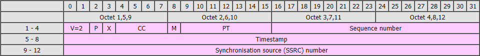
The fields are described below:
- Version
Identifies the version of RTP (currently 2). - Padding
A flag that indicates whether the packet has been appended with padding octets after the payload data. - X (Header extension)
Indicates whether an optional fixed length extension has been added to the RTP header. - CC (CSRC count)
Although not shown on this header diagram, the 12 octet header can optionally be expanded to include a list of contributing sources. Contributing sources are added by mixers, and are only relevant for conferencing application where elements of the data payload have originated from different computers. For point to point communications, CSRCs are not required. - M (Marker)
Allows significant events such as frame boundaries to be marked in the packet stream. - PT (Payload type)
This field identifies the format of the RTP payload and determines its interpretation by the application. - Sequence number
A unique reference number that increments for each RTP packet sent. It allows the receiver to reconstruct the sender’s packet sequence. - Timestamp
The time that this packet was transmitted. This field allows the receiver to buffer and playout the data in a continuous stream. - Synchronisation source (SSRC) number
A randomly chosen number which identifies the source of the data stream.
The complete header
The headers of these three VoIP protocols are sent sequentially before the digitised voice or video samples, which are the payload the RTP header. The result is a 40 octet overhead for every packet of data:

RTP payload
The IP, UDP and RTP headers are followed by the data payload of the RTP header. This comprises digitised samples of voice and video. The length of these samples can vary, but for voice, samples representing 20ms or 30ms or normal.
The selection of this payload duration is a compromise between bandwidth requirements and quality. Smaller payloads demand higher bandwidth per channel because the header length remains at forty octets. However, as payloads are increased, the overall delay of the system will increase, and the system will be more susceptible to the loss of individual packets by the network.
We discuss the bandwidth required for the transmission of VoIP protocols this subject in more detail in our technical paper, VoIP Bandwidth Requirements.
It’s fascinating to learn that a voice over IP system has a hierarchical layering to its structure. A friend of mine might need such a service someday because he plans to start his own marketing firm soon. Timely and effective communication will be key in his success for sure.